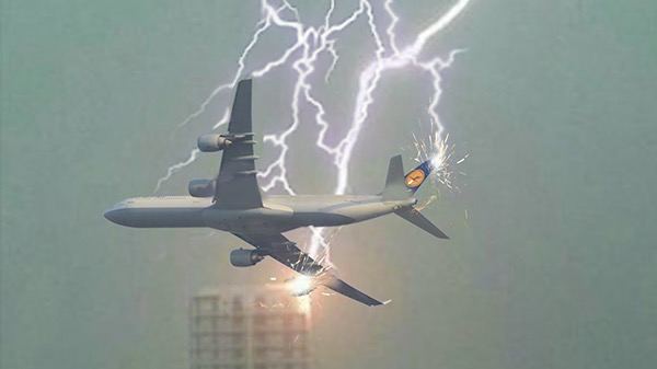
Lightning is a natural phenomenon that has fascinated mankind since way back in history. Different cultures and religions held different beliefs about it over many generations; attributes that generally linked it to a supernatural event, a weapon or manifestation of God or gods. However, man’s insatiable curiosity to unravel natural mysteries eventually led to the discovery that lightning was a form of electricity. Ever since then, this knowledge has enhanced the development of lightning safety inventions both for ground infrastructure and aerial vehicles. Airplanes transport people and goods throughout the year, and quite often their flight paths pass through weather conditions that have high potential for lightning strikes. It is generally estimated that on average an airplane can be struck by lightning at least once each year; and based on the number of flights that happen every day it is an event that is highly likely to occur daily. In this article we will explain effects of lightning on airplanes and features that make it possible for them to make successful flights everyday despite the existence of lightning strike threats.
Lightning formation
Lightning is a product of flow of high electrical current through the air. It can occur within a cloud, between two clouds or between a cloud and the ground. Its formation begins with the sun heating the ground causing warm air to rise and form clouds. A cloud comprises of two forms of precipitation; ice crystals and supercooled water droplets. Movements of air currents (updrafts and downdrafts) and the forms of precipitation within the cloud results in collisions of the molecules with each other; consequently knocking off electrons from some of them. Up going molecules tend to loose electrons causing them to gain an overall positive charge while those going down gain electrons and hence accumulate an overall negative charge. As the cloud grows in height, it extends down near the ground which tends to be positively charged relative to the lower part of the cloud.
Air does not conduct electricity, and therefore, the air spaces between charged regions within the same cloud, or between two charged clouds, or between a cloud and the ground; forms an insulation or barrier which prevents opposite charges in close proximity from flowing freely to neutralize each other. However, a time comes when charges between two oppositely charged points, or two separate clouds, or a cloud and the ground; become so high that the potential difference between the two points rises to a value high enough to overcome the insulation strength of the air.
At this point, the charges will have risen to tens of thousands of volts per inch, resulting in a high electrical tension between this charged region and the air around it. A point is reached when the high electric tension causes a separation in the immediate air molecules; splitting them into positive ions and free electrons; an occurrence called Ionization. Air in this state, or Ionized air, is called Plasma and is electrically conductive. The process emits energy in form of heat. This usually is the beginning of a lightning strike. The process continues more like a chain reaction, through air molecules between the highly charged regions until a complete path is formed for the charges to neutralise each other.

The accumulated electrons on the negatively charged region thus flow rapidly towards the positively charged point; resulting in a high instantaneous electrical current flow through the conductive path created. The heat generated causes two noticeable effects: First it raises the temperature of air molecules along the ionized path, causing them to glow. this is what we usually see and refer to as a lightning streak; and second the heated air molecules undergo rapid expansion followed consequently by a contraction after the flow abates. This rapid expansion of air and the consequent contraction creates a sound wave, which we normally hear and refer to as thunder.
Lightning can attach onto an airplane in two ways. The first case occurs when planes fly too close to a lightning flash and the lightning path is diverted to the airplane, such that its airframe also becomes part of the path. In the second scenario, the lightning flash is usually triggered by airplanes flying into regions with high charges that the leader of the lightning bolt originates from the aircraft itself. Rain clouds which contain suitable conditions for lightning formation usually hang at heights of about 1 to 2 kms above the ground surface and can grow upwards to a height more than 12 Kms (39,000 feet), reaching cruising altitudes of jet airliners. This means that airplanes can encounter lightning throughout a large range of their flying altitudes. High altitude strikes, however, are rare. Most of the cases occur at lower altitudes, mostly below 6 kms (20,000 feet) during climbs or descent.
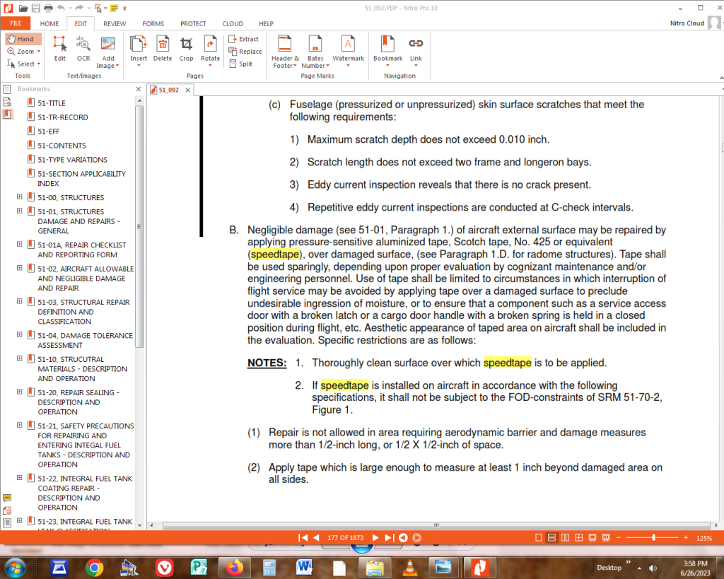
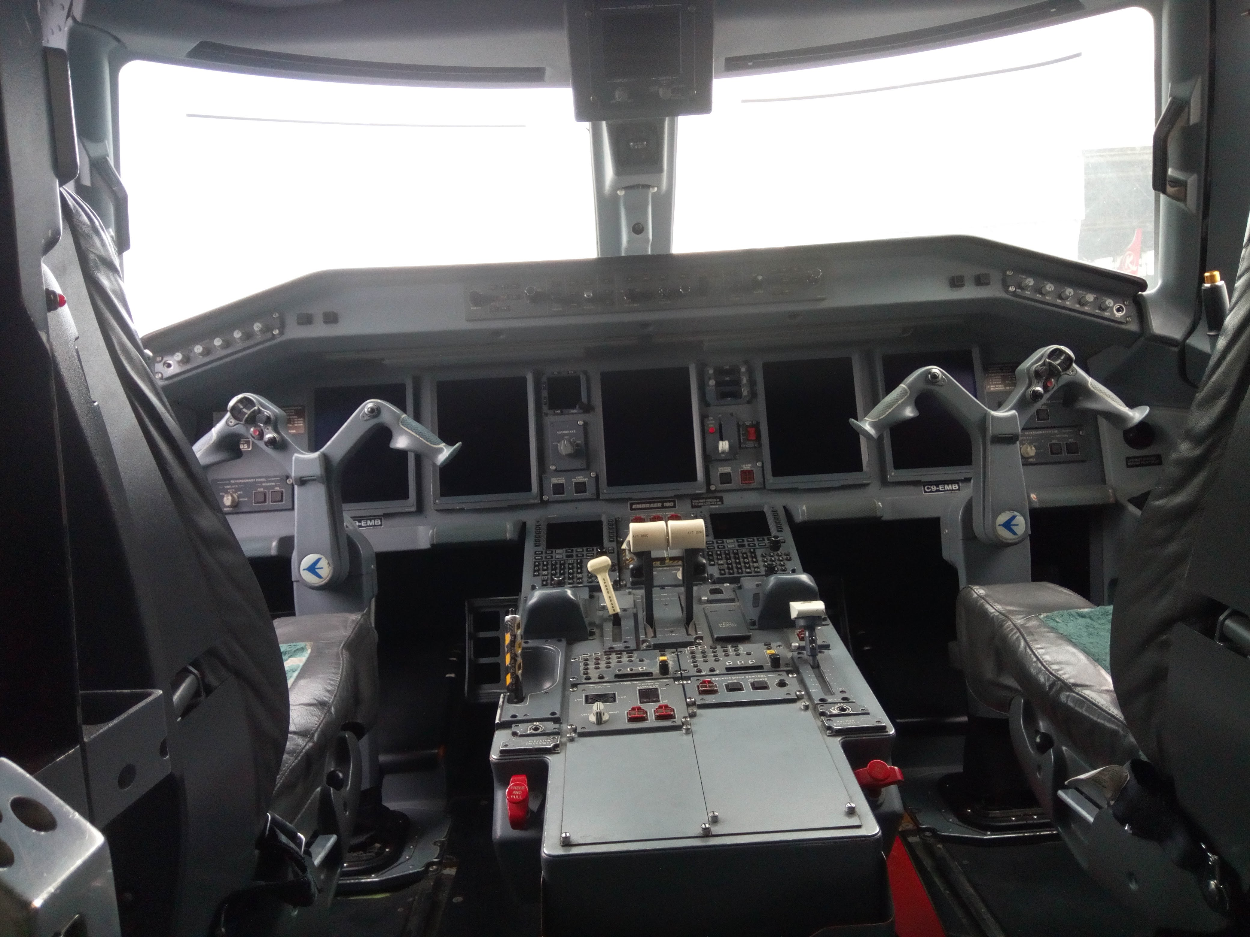
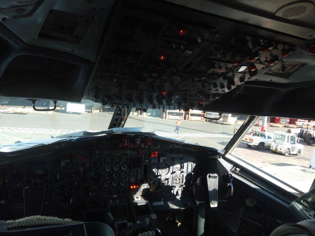
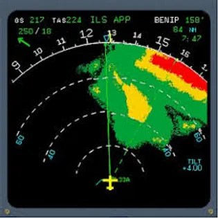
At present, airplanes are not equipped with lightning detection instruments. There is only one available equipment that can help pilots to avoid flying into possible lightning conditions. That is the weather radar. The equipment is capable of detecting the amounts of precipitation within the airspace ahead; but it does not have the capability to detect lightning. It operates by emitting radio frequency waves and receiving reflected waves (echoes) from precipitation particles or water droplets in the air. It then analyses the received signals and processes them to give weather conditions display. A display unit for the weather radar is installed in the flight deck. Clouds are usually displayed with varying colours, corresponding to the amount of precipitation or solid particles that are contained within the various regions of the cloud. A region with heavy precipitation is displayed in a darker shade of red, moderate shows yellow, and that with light amounts will be in green. This information serves an important role as it helps pilots to avoid flying into regions that might contain ideal conditions for lightning formation, heavy rainfall, hail or icing conditions.
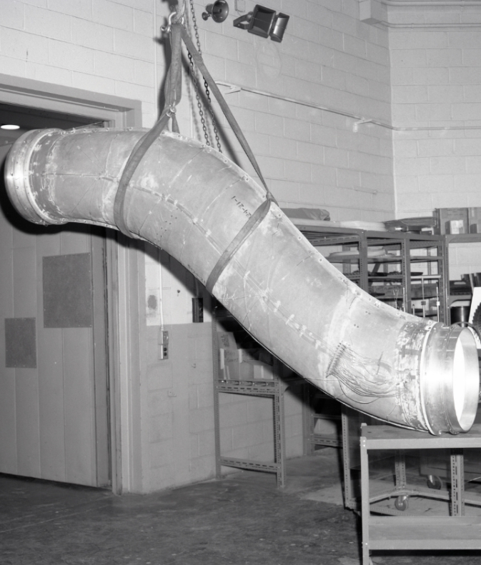
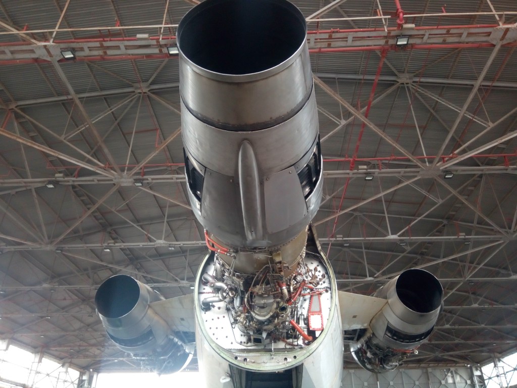
Lightning has the potential to cause several destructive effects to airplanes. When lightning current attaches on the airframe of an airplane it is likely to cause; physical damage to parts or components, fire ignition, interference with transmission of communication and navigation signals, damage to onboard electronic equipment, damage to engine components including gears and electronic engine components, jamming of flight controls when high lightning currents arc across movable hinge joints, and magnetisation of ferrous metal parts like landing gears and flap tracks which usually contain stainless steel parts. Lightning that does not attach to airplanes also has effects, several of which have been known to be fatal. Some of these include interference with communication and navigation signals, fire ignition and possible engine surges or flame-out. The later happens when lightning occurs near the inlet of an engine. Both the heated air by lightning plasma, and the pressure wave due to sudden expansion of air, when ingested by the engine cause compressor surges which can eventually lead to a flameout of the combustion chamber.
Fatal cases involving lightning have also occurred in the past, the most severe one being that of PAN AM Flight 214. The aircraft, a Boeing 707 was in a holding pattern at an altitude of 5,000 feet (1.5 Kms) near its destination airfield. The crew were waiting for a storm to pass so that they could execute a safe landing. According to the official investigation report into the accident by the NTSB, it was discovered that lightning caused ignition of fuel vapours in the left main fuel tank of the aircraft, resulting in a mid-air explosion of its left wing. The plane plummeted towards the ground while engulfed in flames; eventually culminating in its total destruction and loss of all lives on board.


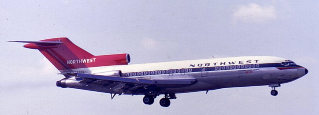
A memorial stone to remember victims of flight 214 crash (left) and an Image of a Boeing 707 (right)
Another effect of lightning on airplanes is disturbances or disruptions to the operation of electronic equipment. This effect is based on the fact that flow of electric current through a conductive medium induces an electromagnetic field around it. High electrical current discharge associated with lightning generates strong electromagnetic fields, which cause interference to electromagnetic waves that usually relay both communication and navigation signals to airplanes. This kind of interference which is propagated through the air is known as Radiated Electromagnetic interference (EMI). It causes distortion to transmitted radio signals and also has the potential to inflict damage to on board electronic equipment. A second type of EMI associated with lightning is known as Conducted EMI. This results from the flow of electrical current through the structure of an airplane. The flow generates electromagnetic fields along the path of conductors which is also capable of causing operational disturbances or damage to electronic equipment.
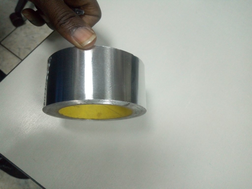
It is therefore mandatory that Lightning strike protection features be incorporated into designs of airplanes, to guarantee continued normal operation and safety of flights. This is called Lightning Strike Protection (LSP). It is achieved by incorporating conductive features into aircraft structures so that external electrical currents that attach onto them will find a conductive path and thus pass through and exit safely without causing damage. Besides this, the protection also aims to block radiated EMI originating from externally and not only from lightning events alone, but many other sources as well.
Aluminium alloys were formerly the main materials used almost entirely in the construction of airplane outer skins and other structural members. These had excellent electrical conductivity properties, such that even high electrical currents associated with lightning would safely enter an aircraft structure and be conducted away quickly and easily with no effect. However later use of composite materials in the construction of some parts; and nowadays having replaced aluminium alloys almost entirely, elevates the risks of lightning effects to a large extent. Composites are preferred due to their outstanding high strength to weight ratio. Their application as structural members reduces the overall empty weight of the aircraft and as a result increasing the payload and fuel efficiencies; but they are poor electrical conductors, and hence vulnerable to lighting strike damage. A means to provide protection for them must therefore be incorporated to make them safe while in use as structural members on airplanes.
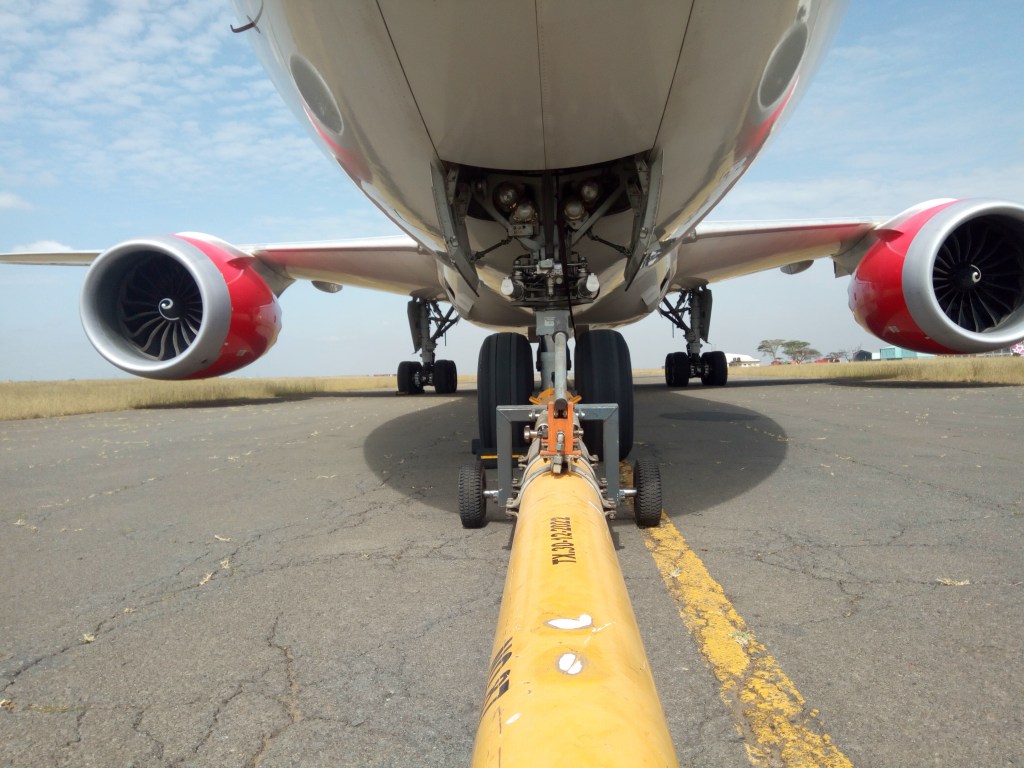
Some parts of airplanes are more vulnerable to lighting strikes than others; and for this reason, different locations are categorised based on the likelihood of lightning to attach onto them. Pointed or protruding or extreme ends of airplanes are usually the most likely parts to attract lightning . This is due to the tendency of electrical charges to accumulate at these locations and therefore acting as a point of attraction to opposite charges. Most prone locations include the nose, wingtips, engine inlets (nacelles) and the rear empennage. These are categorised as zone 1A regions. Low risk areas like the fuselage are classified as zone 2A. Both these regions have to meet certain lightning safety requirements. High risk zones must be able to withstand multiple lightning strikes as well as a maximum current of 20,000 Amperes. The rest of the fuselage must be wholly conductive to be able to facilitate entry and consequently exit of lightning currents. This is important because based on average flight speeds for commercial airliners, an aircraft would have flown a distance more than its own length within the period that it takes a lightning strike to begin and end. This means that should an aircraft get caught between a lightning path, then the points of attachment (entry and exit) of lightning current would not remain constant but will shift rapidly across its length.

By making the outer structure of the aircraft conductive, it also acts like a Faraday’s cage; blocking external electric charges and electromagnetic fields from entering inside the airplane structure and hence, shielding internal electronic equipment from external interference. This, however, also blocks radio frequency signals used both for communication and navigation from penetrating into the airplane structure; and therefore making it a necessity that antennas and transceivers be located outside this ‘cage’. This is usually not a big problem with most communication and navigation antennas, as they are small in size compared to the whole aircraft, and some are normally constructed with an almost flat profile. The antennas are then positioned and electrically grounded either to the under-belly or some to the top of the aircraft fuselage.
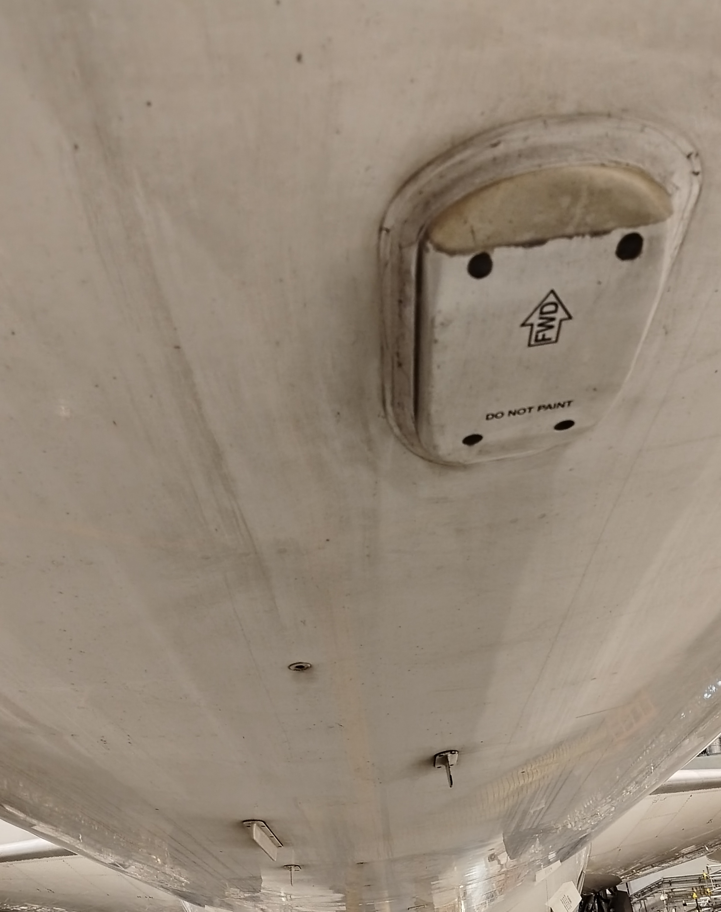

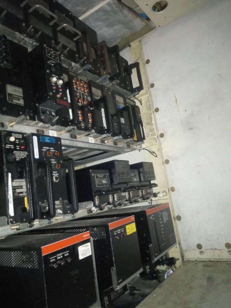
Images of various communication and navigation antennas on under-bellies of commercial transport airplanes.
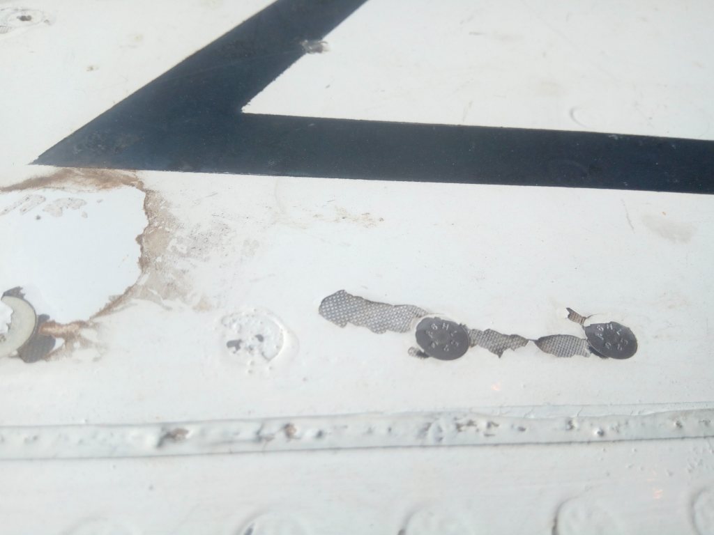
A significant a problem is usually presented with larger transceivers like the weather radar and the satcom transceiver assemblies, which must be positioned outside the main aircraft structure as well. Besides their large sizes these components usually have to be enclosed by materials which do not block electromagnetic signals so as to allow them unrestricted transmission and reception of signals. The shape of the enclosure must also match the aerodynamic profile of their respective locations. The weather radar, scans the area forward of the aircraft and is therefore positioned at the nose of the aircraft. The satcom transceiver on the other hand, transmits and receives signals from satellites in the upper atmosphere or space and it’s most appropriate location is usually on the top surface of the aircraft. Non-conductive composite are the most commonly used materials for constructing the enclosure or fairing, which is also known as the Radome. The Non-conductive or insulating property of the radomes, however, presents a risk of being vulnerable to damage from lightning; and therefore calling for alternate means to provide LSP for them. The most popular method used to accomplish this is by installing lightning diverter strips onto their outer surfaces. The strips are then electorally grounded onto the main structure of the aircraft by a fastener (screw). Diverter strips offer protection by intercepting, or attracting lightning onto themselves, which is then conducted away to the airplane structure via the grounded points. This way, lightning current is diverted away from the non-conductive composite material onto the highly conductive strips, preventing damage that would have resulted from attempted forceful flow of high lightning currents through the non-conductive material. We will leave it at that about diverter strips.
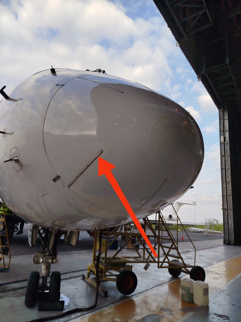
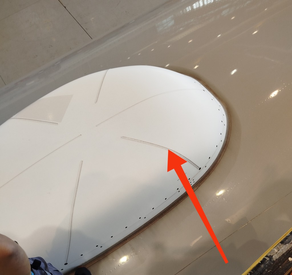
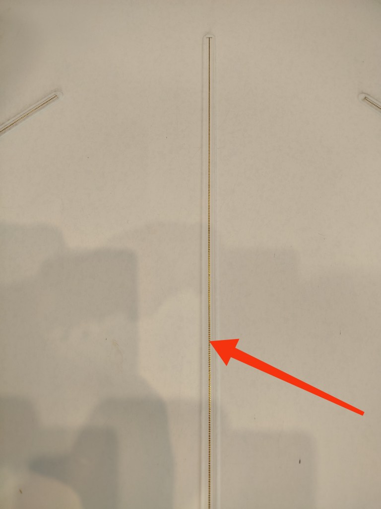
A nose fairing of an Embraer ERJ 190 (left) fitted with solid type diverter strips, a SATCOM antenna on top of a Boeing 777 ( center) fitted with segmented type diverter strips, and a close view of a segmented strip showing the little rounded conductors evenly spaced along it’s length.
Different other methods have been developed that offer satisfactory protection for composites, and every manufacturer has the liberty to use one that is best suited to them. For this reason, different aircraft makes have different LSP features.
The most popular methods include installation of a lightweight conductive mesh on the surface layer of the composite materials; or installation of inter-woven wires within the composite’s laminate plies. An electrical contact is then established between these and a metallic bonding strip or a grounding structure by use of grounding fasteners (screws) at specific locations on each external panel. The grounding fasteners are usually made of a material which has excellent electrical conductivity properties. This way, current is able to be conducted away or channeled across safely until it finally exits the airplane structure.
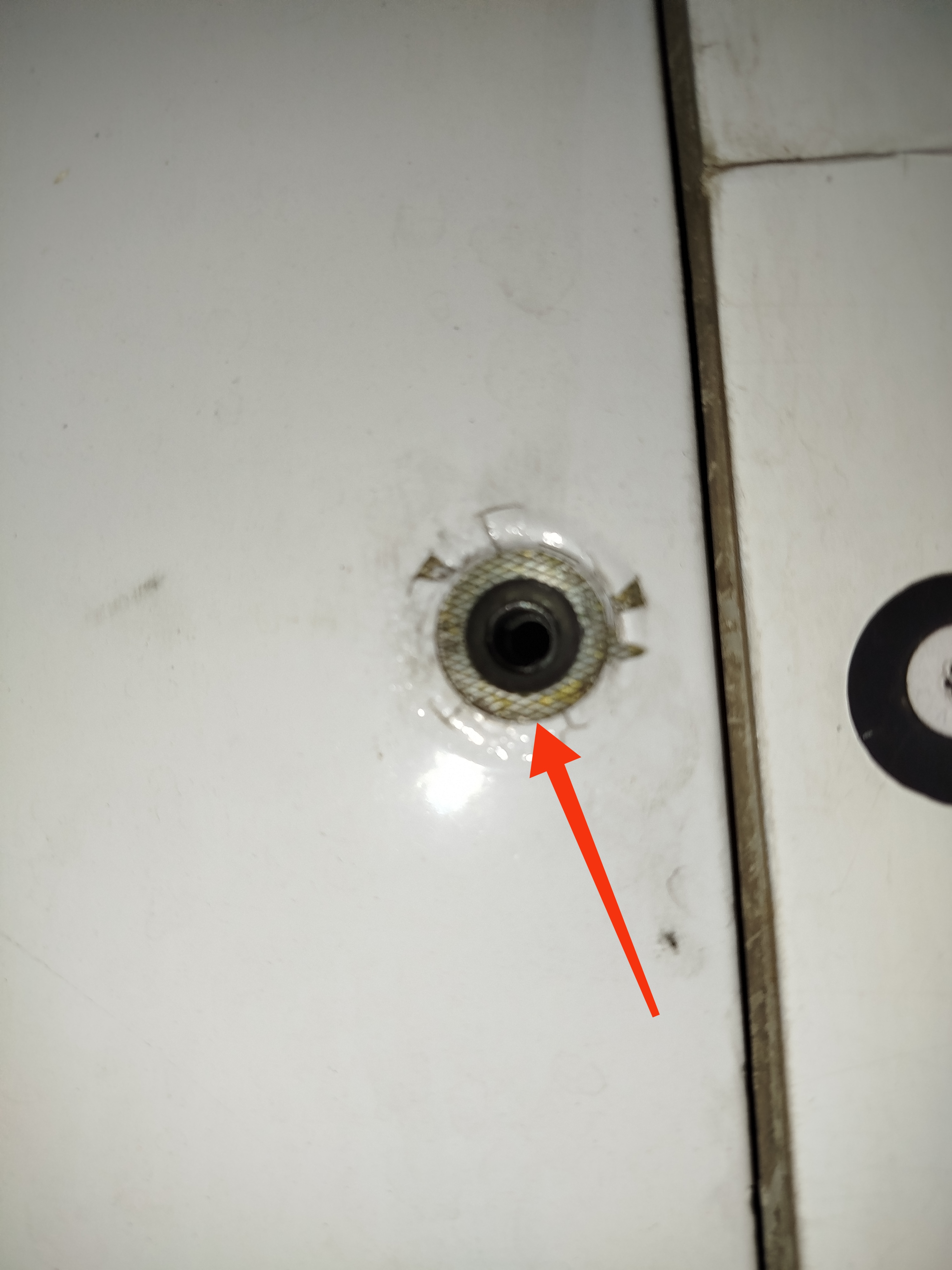
An exposed section of a conductive mesh on a composite aircraft panel (left) and a grounding screw installed with an also conductive cup washer.
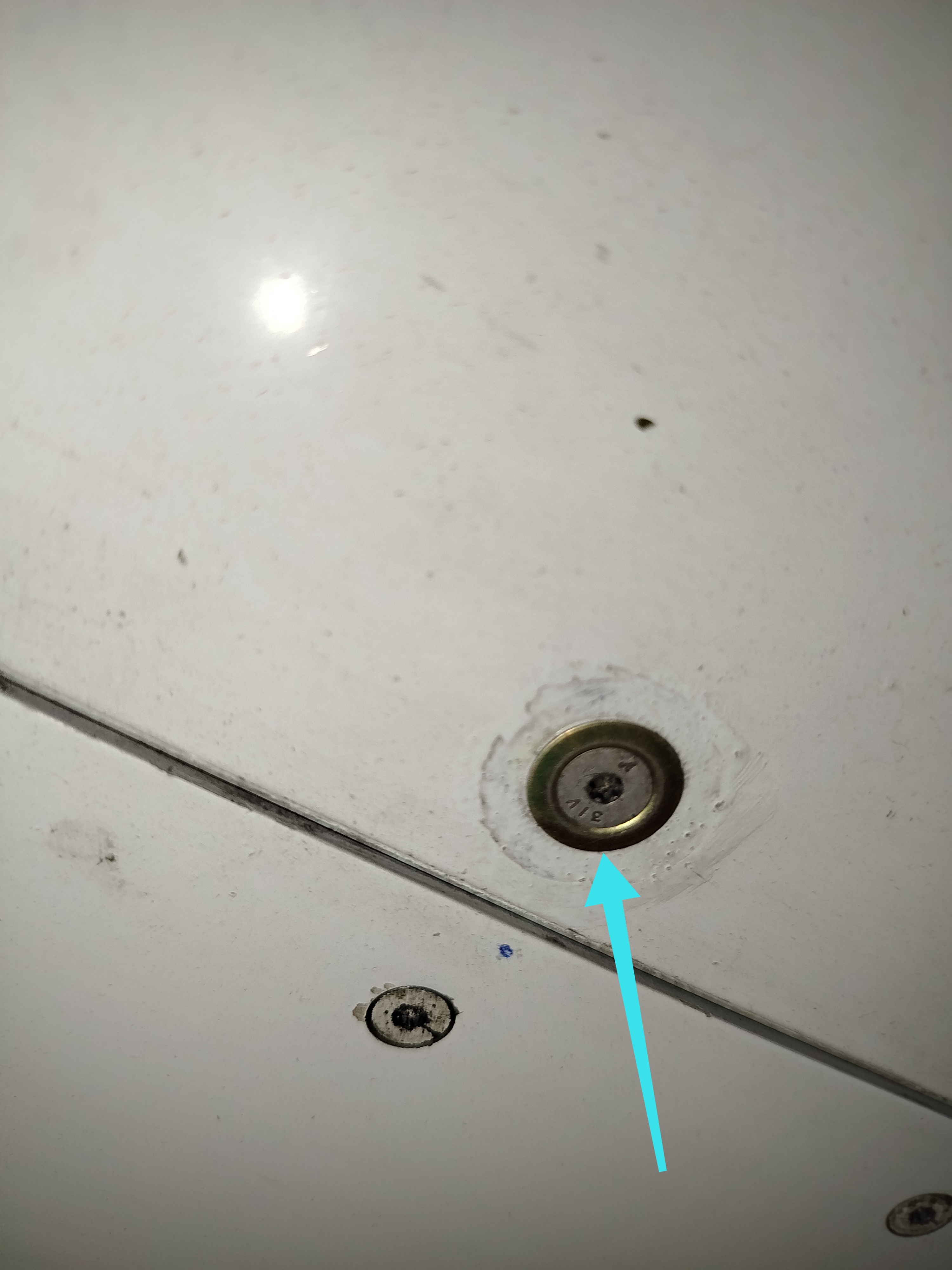
Other practical methods to achieve conductivity on composites for LSP include the use of a thin conductive foil installed on surface ply of composites, use of conductive paints and pastes, use of conductive caulks and sealants between structural joints, use of conductive wire gaskets between aircraft structure and access panels. A typical example of one of these is on Boeing 787, where conductivity is required for static dissipation, which builds up as a result of friction in flight, a special antistatic paste is applied between the outer surface of the panel and the top finish. Once the paste has cured, specific grounding fasteners are then used to establish contact between an exposed section of the paste and a grounding strip or structure. This way, a continuous conductive path is created, and the charges would then travel via a series of strips and bonding jumpers and eventually be dumped overboard through static dischargers or static wicks.
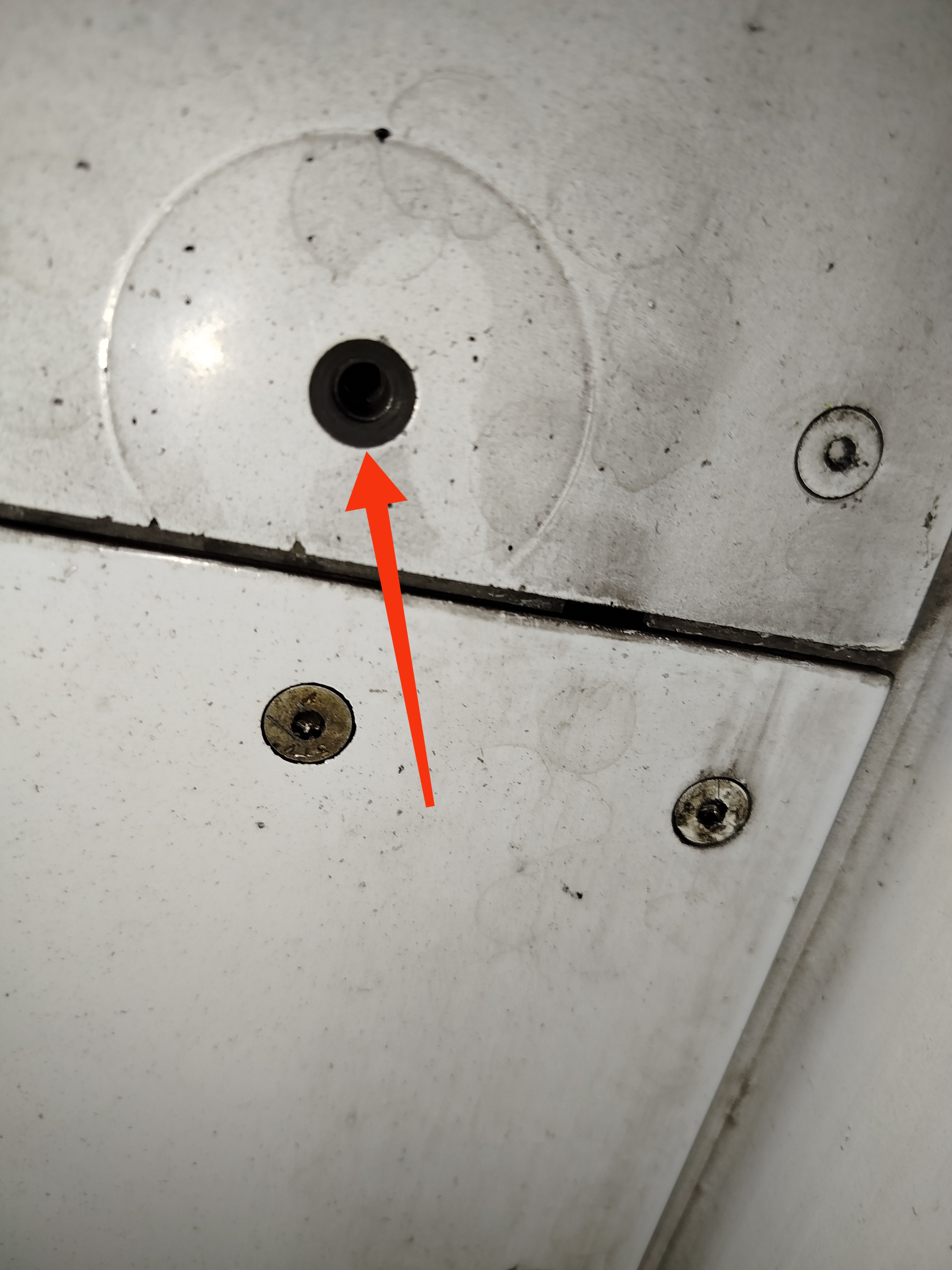
A counter-sunk screw hole section on an airplane panel showing an exposed section with an applied anti-static paste
Static dischargers, or static wicks are not lightning exit provisions, and neither are they lightning arrestors. In fact, these devices usually have high electrical resistance of such values between 6 to 200 megohms, and attempted entry or exit of lightning current through them would cause damage. The purpose of static wicks is to discharge or dump gradually, charges that build up on the airplane surfaces due to friction with the air or any forms of precipitation within the air in flight. These charges would otherwise accumulate and exit through other pointed surfaces and antennas. This would cause distortions to radio frequencies and consequently disrupt communication and navigation signals. To ensure their effectiveness, a conductive path must be established and maintained from all parts of the aircraft to the dischargers.
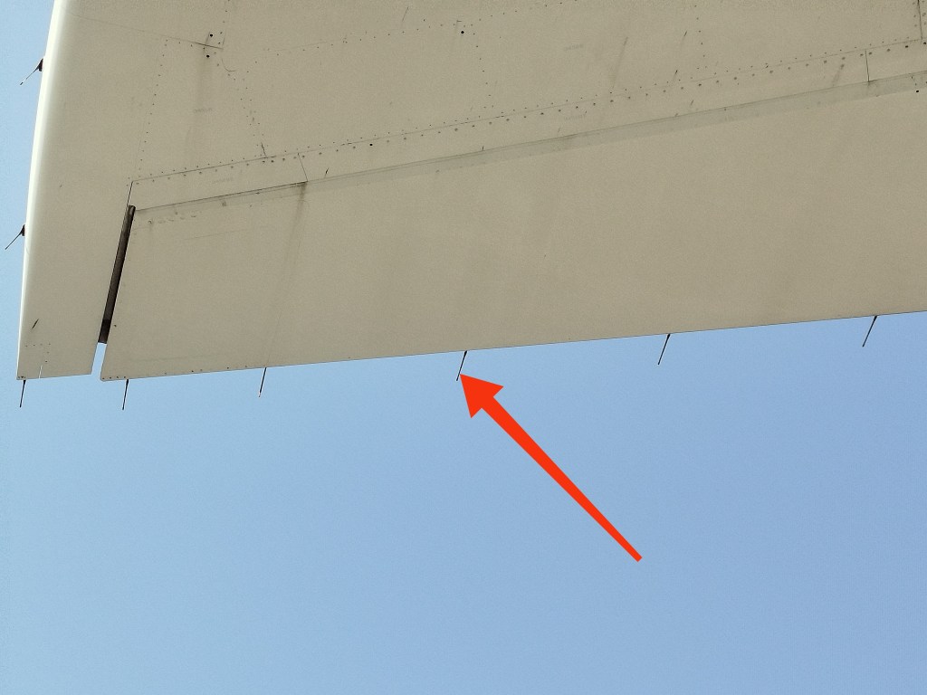
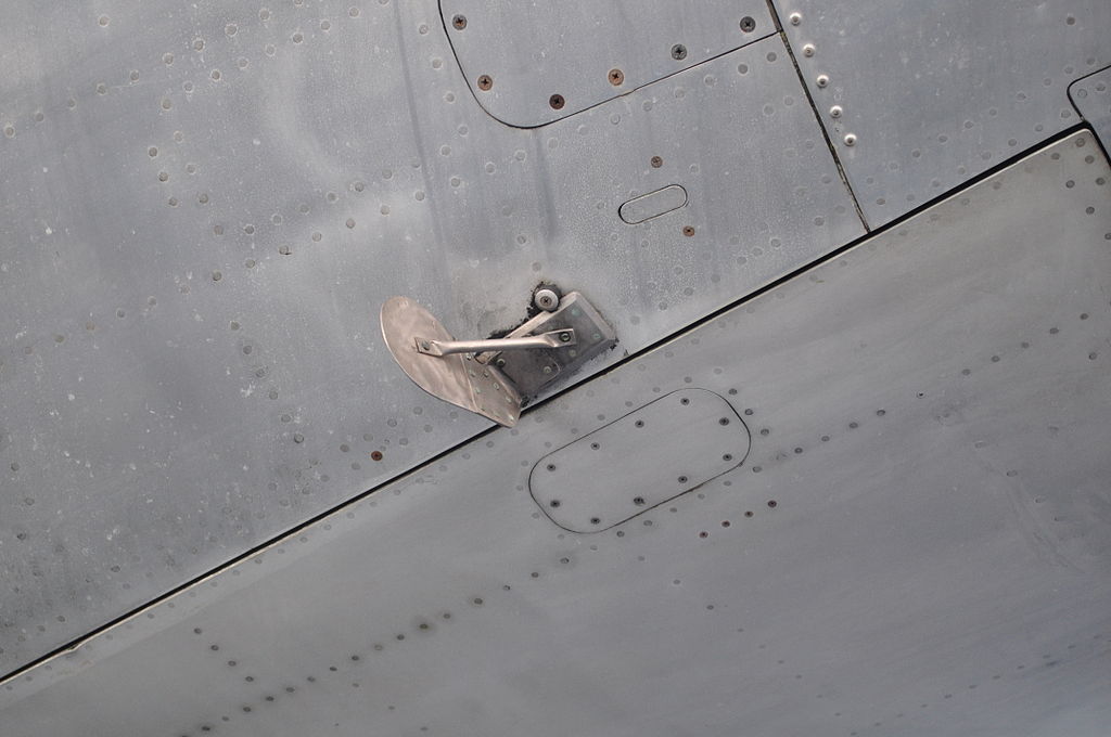
Static wicks at the trailing edge of an elevator and the tip of a horizontal stabiliser of a Boeing 777
Following a suspected lightning strike, airplanes usually undergo a thorough detailed inspection procedure. intended to detect any damage, malfunction or abnormal conditions that might have resulted from the event. Following this, any findings usually call for corrective actions which might include repairs or replacement of damaged parts or components, tests or restoration of any resultant abnormal conditions. An example of an abnormal condition is magnetized ferrous metal parts like we mentioned earlier. This would affect the correct function of the standby compass and therefore have to be demagnetized.